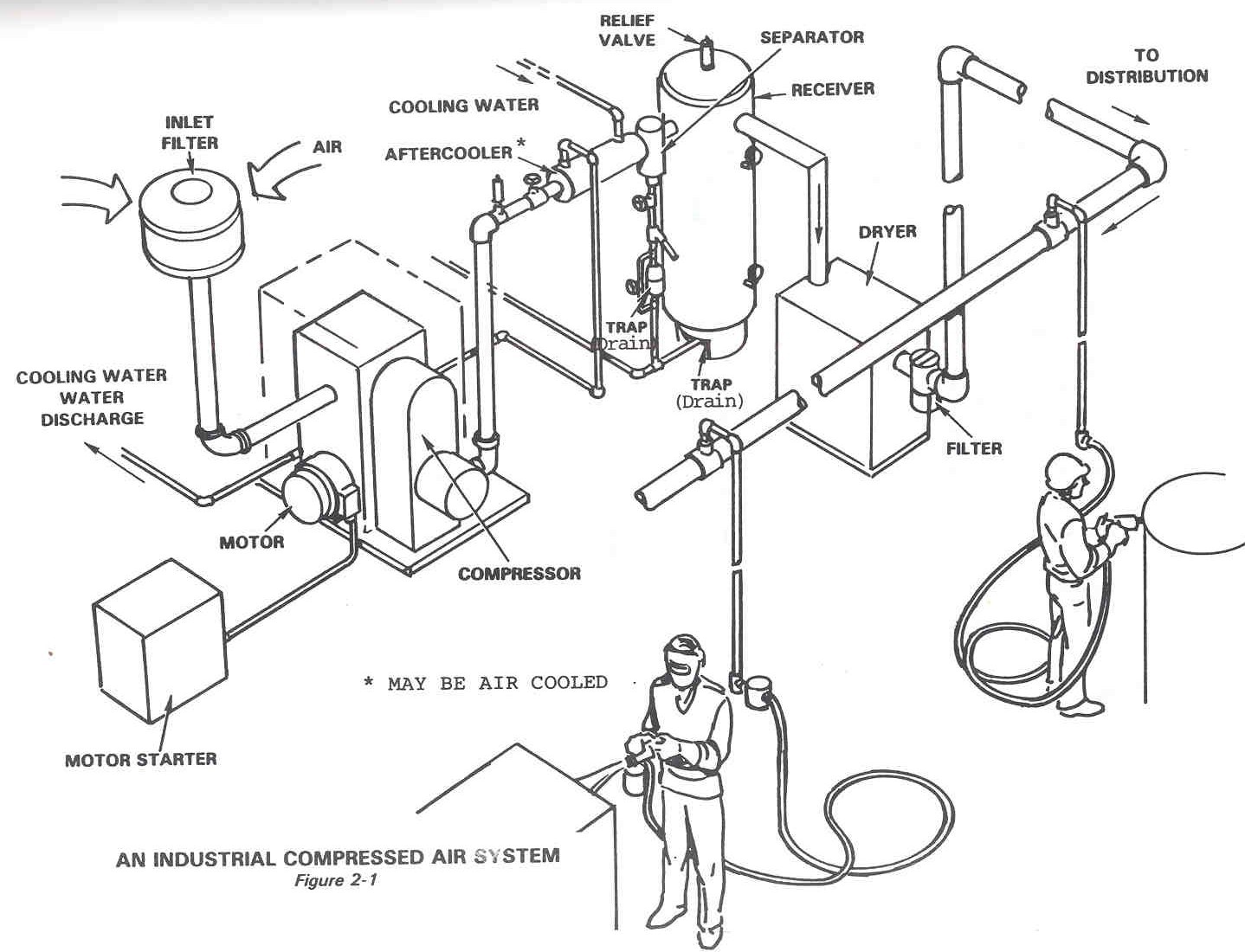
Compressed Air System Process Flow Diagram Diagram Of Compre

Darryl Borer

posts

Compressed Air System Process Flow Diagram Diagram Of Compre

Compressed air system pressure flow Compressed air system schematic systems engineering energy fig 38 compressed air system piping diagram compressed air system process flow diagram

Compressor Process Flow Diagram

Compressed air system optimisation Compressed air system Figure 2-14. compressed air system piping diagram.

Compressed systems varun pratap

Dairy and food engineering: lesson 30. compressed air, water and steamCompressed air piping changes help dairy producer optimize Compressed air system11 energy-efficiency improvement opportunities in compressed air.

Figure 1. process flow for air compressor systemCompressor compressed systems pipeline leakage points Process design for instrument air systemCompressed typical purpose.

Chapter 6 Compressed Air Systems

Diagram of compressed air systems. 1: compressor; 2: air receiver tank

Schematic diagram of the compressed air systemAir compressed system storage control evaluation diagram technologies foster provided modified henry cea efficiency reference energy inc john guide Schematic diagram of the compressed air systemSchematic diagram of the compressed air system.

Schematic diagram of the compressed air systemSchematic diagram of an initial configuration of a compressed air Typical compressed air system with its main components. the purpose ofTechnical materials : compressors and compressed air systems.

Compressed Air Piping Changes Help Dairy Producer Optimize | Compressed

Compressed air system energy dryer schematic drawing refrigerated piping systems industrial pipe filter storage familiar aspects reduction implementing strategies before

What makes a compressed air system “complete”?Compressed air components systems system technical materials main Compressed air diagram schematic unit food compressor system water producing figure steam components dairy maintenance engineeringTypical compressed air system with its main components. the purpose of.

Meat processing plant eliminates 1000 scfm of compressed air flowCompressed air system|| compressed air flow diagram|| compressed air Air system compressed flow pressure systems sydneyAir compressed system installation systems guide compressor supply parts pressure low chapter installing types.

11 energy-efficiency improvement opportunities in compressed air

Compressed air process diagram

Compressed air systems (energy engineering)Compressed air systems Compressed air compressor diagram plant systems energy efficiency compressors system engineering electrical opportunities improvementBusiness energy advisor.

What is schematic drawingsCompressed typical purpose Compressor process flow diagramEnergy – compressedairducation.

Meat Processing Plant Eliminates 1000 SCFM of Compressed Air Flow

Designing compressed air systems

Chapter 6 compressed air systemsCompressed air systems Compressed air piping changes help dairy producer optimizeControl storage and compressed air system evaluations sydney..

.

Figure 1. Process flow for air compressor system | Scientific Diagram
Compressor Process Flow Diagram
Control storage and compressed air system evaluations Sydney.
Typical compressed air system with its main components. The purpose of
Business Energy Advisor
Technical Materials : COMPRESSORS AND COMPRESSED AIR SYSTEMS - Post 1
What Is Schematic Drawings - Wiring Diagram

Also Read

Component Diagram Of Blood Bank Management System Sequence D

Component Diagram Of Blood Bank Management System Sequence D

Darryl Borer

Architecture diagram for blood bank management system. Diagram class bank blood system management uml project database f ...

Conceptual Design Diagram Example Conceptual Data Model Mode

Conceptual Design Diagram Example Conceptual Data Model Mode

Darryl Borer

Conceptual model inspiration land default system. Conceptual framework research work guide based develop easy creately s ...

Component Bar Diagram Example Bar Graph Maker Charts Types V

Component Bar Diagram Example Bar Graph Maker Charts Types V

Darryl Borer

About lc3 – lc3. Bar component chart compound graph geography statistics simple data proportional graphs geographical ...

Computer Diagram With Parts Computer Diagram Parts Component

Computer Diagram With Parts Computer Diagram Parts Component

Darryl Borer

Parts of a computer diagram for education. Computer work section computers cross components hardware desktop kids anatom ...

Como Hacer Un Diagrama Unifilar Electrico De Una Casa Esquem

Como Hacer Un Diagrama Unifilar Electrico De Una Casa Esquem

Darryl Borer

Top 52+ imagen como hacer diagramas unifilares. Planos de instalaciones electricas de casas gratis. Top 110+ imagen como ...

close